Guidance for Packaging Machine Safety


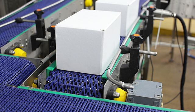
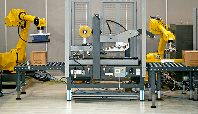
New guidance is now available on how to make packaging machines safe. This will provide much-needed assistance for machines used widely in the food and beverage industry, general manufacturing industry and warehousing/distribution industry. Australian Standards have published 8 new standards to provide guidance for different types of packaging machines:

  1. AS 4024.3401:2018 – Safety of Packaging Machines – Terminology and classification of machines
  2. AS 4024.3403:2018 – Safety of Packaging Machines – Form, fill and seal machines
  3. AS 4024.3404:2018 – Safety of Packaging Machines – Palletisers and depalletisers
  4. AS 4024.3405:2018 – Safety of Packaging Machines – Wrapping machines
  5. AS 4024.3406:2018 – Safety of Packaging Machines – Pallet wrapping machines
  6. AS 4024.3407:2018 – Safety of Packaging Machines – Group and secondary packaging machines
  7. AS 4024.3408:2018 – Safety of Packaging Machines – Strapping machines
  8. AS 4024.3410:2018 – Safety of Packaging Machines – General Requirements

These standards provide consistency with international practice because they are adoptions of the EN 415 series from Europe but be aware some of these standards are quite old. For example AS 4204.3403 is an adoption of a 1999 version standard and AS 4024.3404 is an adoption of a 1997 version standard. This means that many of the document references in these standards are out of date and some of the control measures are lacking when compared to today’s levels of safety, so be aware!

It is always a good idea to formulate the Category / Performance Level (PL) / Safety Integrity Level (SIL) requirement of safety functions based on the risk of the application using methods from current standards, thus using AS/NZS 4024.1501 for Category Selection, AS/NZS 4204.1503 for PL selection and AS 62061 for SIL selection.

It is also a good idea to always investigate what current industry practices are when selecting risk reduction measures. This can be done by referencing any guidance material published on your state WorkSafe website, observing new models of that machine type, exploring how other sites with similar machines provide safety, etc.

That being said, the new Packaging Machine Standards, do provide great assistance for risk assessment of packaging machines because many of the common hazards found on these machines are illustrated. The standards also provide good information on what types of safety measures can be utilised to reduce risk to an appropriate level.


Craig Imrie, Functional Safety Engineer

Written by
Craig Imrie
Functional Safety Engineer (TUV Rheinland #3814/11, Machinery)
Safety Consultant
Rockwell Automation
LISTEN. THINK. SOLVE.


Published: 21 August 2018

Guidance for Light Curtains & Laser Scanners


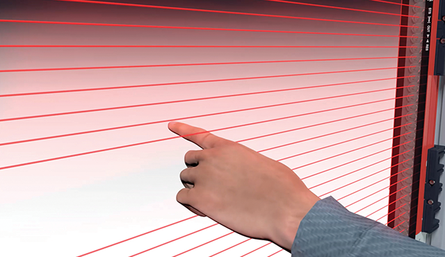
The most misapplied safety devices in the industry are light curtains and laser scanners, common issues with installations include:
  1. Application not suitable for light curtain/scanner, eg; the machine ejects parts, the machine has a long stopping time, environmental influences
  2. Light curtain placed too close to the hazard – Insufficient safety distance 
  3. Scanner safety field size is too small – Insufficient safety distance 
  4. Stopping performance monitoring not provided when it should be
  5. Muting sensors not mounted correctly
In the past, it hasn’t been easy for installers/designers to find guidance on all these topics in the one reference. We have had AS 4024.2801 in Australia since 2008, but this standard only provided sufficient guidance for safety distance calculation which addressed issues 2 and 3 from the above list.
Guidance is now at hand with the new standard AS 4024.2802:2017 being introduced. This standard provides information on all aspects of designing/installing presence sensing system such as light curtains and laser scanners.

AS 4024.2802:2017 covers safety distance calculation to address issues 2 and 3 in the above list, but it does a lot more as well.

It also provides an explanation of how to ensure the application is suitable for presence sensing devices, this guidance can help address issue 1 from the above list.

Issue 5 a major problem in the industry, it is common to see muting sensors mounted incorrectly and this increases the risk of operators inadvertently muting the light curtain and being exposed to hazards. AS 4024.2802:2017 has information on all common muting configurations and provides clear instructions on how the sensors are mounted and the timing sequence of the muting operation.
Issue 4 reflects the fact that many designers/installers aren’t aware of the requirement of stopping performance monitoring. If the light curtain/scanner is used as a trip device then the safety distance is integral to ensure the risk is controlled. If the machine’s stopping time is subject to deterioration (eg: brake wear) then the stopping time of the machine should be monitored. This information can be used to schedule preventative maintenance to ensure the safety risk is controlled and reduce unexpected downtime.

If you design/install or maintain presence sensing systems, such as light curtains or laser scanners, I recommend referencing the new AS 4024.2802:2017 standard.


Published: 8 February 2018

Safety for Collaborative Robots


In recent times there has been a strong growth in the use of robots in Australian manufacturing, thus why collaborative robots is currently a hot topic. These robots are designed to operate in cooperation with humans, which presents some new safety considerations compared to traditional robots that operate behind a safety fence. There is a new Australian Standard, AS 4024.3303:2017, which provides guidance on the process involved to ensure your collaborative robot doesn't pose a threat to its human work colleagues.

A risk assessment must be carried out to determine if a collaborative robot is suitable for the application. This should also include determining the collaborative workspace of the robot and estimating the risk of the hazards so the appropriate risk reduction measures can be applied.

The collaborative workspace is the area where the robot and human co-inhabit during normal operation, see Figure 1 below.
Fig. 1 - The Collaborative Workspace
To reduce the risk associated with robots and humans working in this collaborative workspace one or more of the following methods can be utilised.


Safety-rated Monitored Stop

This method may be used to provide access for the operator to perform tasks, such as loading a part into the end effector. In this method, the robot will move to the collaborative workspace and perform a safety stop. This allows the operator to enter the collaborative workspace and perform their task. Once the operator is out of the collaborative area, the robot can resume normal operation. If the operator enters the collaborative workspace, when the robot is moving in the collaborative workspace, the robot will perform a safety stop and need to be manually reset.

The robot system must be able to detect the presence of an operator inside the collaborative workspace. The size of the collaborative workspace must be determined to take into consideration the speed of the robot, the reaction time of the robot, stopping time of the robot, speed of human movement and resolution of the system used to detect the presence of the operator.


Hand Guiding

This method works similar to the "Safety-rated monitored stop" however, once the operator is inside the collaborative workspace, they can operate the robot with a hand guiding device. This allows the operator to manually control the robot in close proximity for detailed tasks. When the robot is manually controlled, it will perform its movements at a controlled speed deemed acceptable from a risk assessment. If the operator releases the hand guiding device, the robot will stop and when the operator has left the collaborative workspace, the robot can resume normal operation.


Speed and Separation

In this method, the robot and operator can work at the same time in the collaborative workspace. The robot maintains a protective separation distance from the operator. If the distance between the operator and robot becomes less than the protective separation distance the robot will stop.

The speed of the robot must be monitored because the protective separation distance is reliant on the speed of the robot. The protective separation distance is also reliant on the on the robot’s reaction time and the accuracy/resolution of the system used to detect the distance of the operator.

The robot may change its speed depending on the position of the operator to reduce the protective separation distance or the robot may use alternative paths that ensure the protective separation distance is maintained.


Power and Force Limiting

In this method, the robot and operator can work at the same time in the collaborative workspace and contact between the operator and robot can occur. The energy and force of these collisions are limited below an established threshold limit. A risk assessment process is used in conjunction with data from Annex A of the standard, to determine the suitable energy and force thresholds for the tasks to be performed.

The robot keeps energy and force of contact below the threshold by:

  • Increasing contact surface areas; rounded edges, smoothed edges, etc.
  • Absorbing energy; using padding/cushioning, deformable components, etc.
  • Limiting forces, speed
  • Using sensors to anticipate collisions 

When considering a collaborative robot, it is essential that a risk assessment process is conducted to understand the risks associated with the application. With the use of the new standard, AS 4024.3303:2017, the appropriate collaborative methods can be selected. The standard also provides guidance, on what safety features the robot requires for each collaborative method.


Published: 25 July 2017

How do I validate my Safety System?


The most common step that is not performed or performed incorrectly when implementing a safety system is validation. This step is essential to confirm the specification and conformity of the safety system, however many people are unsure how to validate or don't even consider performing a validation.

Here are some common mistakes made with validation:

No Specification

You can’t validate an unspecified safety system, thus if there is no specification document then what are you validating?

The specification document has two purposes:
  1. It provides a framework for the system to be designed
  2. It provides a specification to validate

The specification should explain the following:
  1. The functional behaviour of the safety system - For example if the system is an E-Stop the specification should explain; how the E-Stop is initiated, what hazardous movements are inhibited by the E-Stop, what Stop Category is performed, how quickly are these movements inhibited, how is the system reset to allow machine operation to continue, etc.
  2. Operational and environmental conditions
  3. Integrity Requirements - What is the level of risk reduction required by the safety system? This can be measured by a required Safety Category (CAT), Performance Level (PL) or Safety Integrity Level (SIL)
Once the Specification exists then the system can be validated according to its functional, environmental and integrity requirements.

Only Normal Operation of Safety System is Tested

It is common for validation to be performed on a safety system with no fault simulation testing.

For example, if validating an E-Stop the machine is started under its maximum expected operational load and the E-Stop hit. The safety function is validated by confirming the hazardous movements have been ceased in the required time according to the specification and the machine can’t be restarted until the E-Stop operator is manually reset.


The above validation may prove the functional behaviour of the E-Stop but many safety systems also require fault simulation to validate their integrity requirement. If the above E-Stop had a requirement of CAT 3, then all single fault modes would need to be simulated to confirm that the system will not lose safety function due to a single fault.

No Documentation

As like any activity performed during the implementation of a safety system, validation does not exist if it is not documented. All relevant analysis, tests reports, calculations, data sheets, etc. must be recorded to prove the process undertaken.

For help with validation plans, register for the NHP Safety Reference Guide, in the 'Safety Function Document' section there are numerous examples of pre-engineered Safety Functions with validation plans at the back of each document.

For more information on the process of validation, activities to be performed and the documentation required reference AS 4024.1502-2006.


Published: 18 May 2017

What makes a contactor a safety contactor?


A common question is; Do I need to use safety contactors in safety-related control systems?

So, what makes a contactor a safety contactor? These devices are purpose built for safety applications with many design principles built into the product. Like most safety devices, third-party certification provides a good reassurance that the product is appropriate for safety applications. NHP safety contactors are independently certified by Suva Accredited Certification Body.

As required in AS/NZS 4024.1501/1502/1503 the use of basic and well-tried safety principles must be considered for any safety control system for Category 1-4. The design and construction of safety contactors incorporate many of these safety principles. Some of these principles include:

Pictured: 37KW 3P 110V AC COIL 4NC
AUXILIARY Safety Contactor

True auxiliary indication

The auxiliary contacts that provide feedback to the safety system should use proven techniques such as positive guided/mechanically linked or mirror contacts to ensure a true indication of the contactor's state. In AS/NZS 4024.1502 the use of these techniques is defined as a well-tried safety principle and is required for Category 1-4.

No manual operation

Unlike standard contactors that can be easily operated from the front of the device, safety contactors do not allow for manual operation from the front of the contactor. This design feature avoids the possibility of personnel creating an unsafe state due to unexpected start-up. In AS/NZS 4024.1502 the prevention of unexpected start-up is defined as a basic safety principle required for Category B-4.

Securely fixed auxiliary contact block

The auxiliary contacts on safety contactors are permanently or securely fixed to the device, this avoids the possibility of the auxiliary contacts becoming separated from the contactor due to environmental causes (eg. Vibration) and makes intentional tampering more difficult. In AS/NZS 4024.1502 the secure fixing of these contacts is defined as a basic safety principle, required for Category B-4.

Reliability data

When designing safety systems to the standards AS/NZS 4024.1503 or AS 62061, reliability data needs to be obtained for the safety devices. Safety contactors have reliability data in the form of a B10d value.

Easily identifiable

To reduce the chances of unintended misuse of the safety system, safety contactors may be easily identifiable compared to standard contactors, i.e.: The safety contactor may be a different colour. This feature reduces the chances of accidental tampering with the safety system.

Other design considerations when selecting contactors in a safety-related control system include:

  • Consider environmental influences of the application such as temperature, vibration, existence of dust or other contaminants, this is a basic safety principle from AS/NZS 4024.1502
  • Consider over-dimensioning the contactor to reduce dangerous failure modes, this is a well-tried safety principle from AS/NZS 4024.1502
  • Where available use contactor coils with built in surge suppression, this is a basic safety principle out of AS/NZS 4024.1502
  • Ensure all circuits have relevant protection devices


Published: 17 January 2017

How to Select the Correct Safe Guard


When should you install a fixed guard as opposed to an interlocked guard?

Is a bolted guard a permanent fixed guard?

When is it acceptable to replace physical guards with light curtains?

These are common questions people have when selecting the appropriate guarding for their machinery. Guidance on selecting the appropriate guard is available in the Work Health and Safety legislation, section 4 of the Code of Practice, "Managing the Risks of Plant in the Workplace" explains this process. This is based on clause 208 of the Work Health and Safety Regulations (Current legislation for all states and territories except for WA and Victoria).

Here's what the code of practice says about selecting your safe guard:

If access to the area of the machine is not needed during operation, maintenance or cleaning then a permanent fixed safe guard is required. What is a permanent fixed safe guard? The code of practice states this guard is welded or incorporated into the body of the machine, thus a bolted guard is not a permanent fixed safe guard.

If access to the area of the machine is require during operation, maintenance or cleaning then an interlocked guard can be used. This guard will have a safety control system that will cease any relevant hazardous energy to the machine when the safe guard is not in a closed position.

If it's not reasonable to use a permanent fixed safe guard or interlocked safe guard then a fixed safe guard can be used. A fixed safe guard can be removed and replaced with the aid of a special tool, such as a coded spanner or Allen key. Thus a bolted guard would be classed as a fixed safe guard.

If none of the above physical guarding options are practicable, then a presence sensing system, such as light curtains or laser scanners can be used. A common example of this would be a conveyor that transports goods into a robotic cell, if a physical guard was used then the goods would be blocked in entering the cell whereas a light curtain will allow the goods to enter the cell in a safe manner.

The most common query people have about the above guidance is: When should I use an Interlocked Guard or a Fixed Guard?

The interlocked guard is the first option when access is required because a safety control system is protecting the operator from the hazards on the machine. When using fixed guarding we are relying on human behavior to ensure three things:

  1. The hazardous energy has been isolated before the safe guard is removed
  2. The hazardous energy will remain isolated while the safe guard is removed
  3. The guard is replaced before the hazardous energy is resupplied to the machine

Thus two considerations should be made when deciding if a fixed guard is appropriate:

  1. Frequency of Access - The more frequently we rely on human behavior, the more likely the process will fail. If access is required multiple times a week or during normal operation it would be recommended to use an interlocked guard
  2. People performing the task - For access through a fixed guard the operator must be trained on the isolation procedure of the machine, this training must be refreshed and documented. If this knowledge can't be relied on then an interlocked guard should be used.


Published: 6 October 2016

How do you future-proof your safety systems?


Looking through machine safety standards there is plenty of guidance for the early phases of machine safety system life cycles, by this I mean you can find good guidance to explain the following activities:
  • Select the required integrity level; CAT/PL/SIL
  • Design the safety system
  • Verify the system design
  • Validate the safety system
But what guidance is available for the operation phase of the safety system? Safety systems can be operational for 10 to 20 years, sometimes even longer! Is it reasonable to expect application parameters won't change the requirements of the safety system over that extended period of time?

Requirements can change dramatically over the life of a safety system for example here are some parameters that could affect the suitability of the current safety system:
  • The uses of the machine 
  • Speed of throughput
  • Frequency/duration of safety demands on the system
  • Stopping times of the equipment
The need to design systems to take consideration of the above changes is becoming more prevalent. Functional safety standards such as AS 62061 mention these factors as prompters for safety system modification, but how can you reliably identify these parameter changes?

Relying on manual monitoring of the safety system parameters causes extra work and is susceptible to human complacency/error.

With the ability to have high levels of data sharing from modern safety systems to standard control systems, it is possible to create this parameter checking as an automated function of the control system. Thus if the use of the machine is changed in a way that effects the safety system's suitability, this will be flagged by the control system and initiate the appropriate modification process.

The most common example of the above concept is Stopping Performance Monitoring (SPM), which is a requirement out of IEC/TS 62046. SPM should be performed when presence sensing systems such as light curtains, safety mats or laser scanners are used as a trip device and the stopping performance of the machine can be subject to deterioration, due to wear of brakes, valves, etc. SPM could be achieved by the machine control system monitoring the stopping performance of the machine and comparing this result to the calculated stopping time used for the safety distance calculation of the presence sensing system. Once the calculated stopping time is exceeded the control system could initiate a safety stop, provide information to the operator of this condition and not allow operation until the system is restored to its acceptable state.

Preventative warnings could be provided by the control system as the stopping performance approaches the calculated stopping time, thus the braking system can be repaired in upcoming scheduled maintenance. Downtime is then avoided and the level of safety is maintained.

Require more information about how modern safety systems with increased integration can assist? 

Craig may be able to assist you with the above mentioned issues, so please reach out via email - cimrie@nhp.com.au.

Craig has been a Safety Specialist with NHP Electrical Engineering Products since 2007. He is also a committee member at Standards Australia and is a TUV Rheinland certified Functional Safety engineer.
Craig Imrie


Published: 6 July 2016

PL and SIL merger cancelled. What does it mean for AS 4024.1?


For those who are designing machine safety control systems to achieve international standards you may have been aware of the process in place to merge the two current standards. This would result in a new standard, IEC/ISO 17305, which would merge the methods of Performance Levels (PL as per ISO 13849.1:2015) and Safety Integrity Level (SIL as per IEC 62061).

This process was seen as a positive step for machine safety designers as we would finally have one unified standard that everyone would design their systems to, instead of the confusion of having multiple standards running concurrently. However this merger process has now been cancelled without a guarantee of when or if the process will be restarted.

So what is the relevance of this to Australian Standards?
Our Australian Standard, AS 4024, adopts directly from international standards and as stated in AS 4024.1100 the future direction of the control system section was dependent on the merged standard:
It is envisaged that on completion of the work of Joint Working Group 1 of ISO/TC 199 and IEC/TC 44, combining ISO 13849-1:2006 and IEC 62061, the resulting unified Standard will replace both
Parts 1501 and 1503 in the next revision of the AS 4024.1 series

So what does this mean for the future direction of AS 4024.1? Well that seems to be up in the air at the moment.

Potentially the next revision of AS 4024.1 will see Safety Categories disappear and Performance Levels remain. Another option may be Safety Categories remain as an option for safety control systems that consist of simple devices, such as safety relays, safety contactors, safety valves, etc.

There may be advantages of this second option for the following reasons:
  • The Australian industry has much more familiarity and knowledge of Safety Categories compared to PL or SIL
  • Safety Categories provide a simple method to design safety control systems
  • When applied correctly Safety Categories provide adequate risk reduction
  • International systems using PL will still be designed to a Safety Category architecture
What do you think? 
If you have a comment or opinion on what the future direction of safety control systems should be in AS 4024.1 please leave a comment below.

Feedback from the industry is essential so the committee can ensure the standard reflects the industry’s needs.


Published: 22 March 2016

New Conveyor Safety Standards Are Here!


As of August 2015, AS 1755 has been superseded by a new set of conveyor safety standards. For those who aren’t familiar with AS 1755, this is why it's a big deal:
  • AS 1755 has been the Australian standard for conveyor safety since 1986
  • It is the code of practice for conveyor safety in South Australia and referenced as guidance for conveyor safety in every other state and territory’s code of practice
  • Conveyors are one of the most prevalent types of machinery in Australian industry and a significant cause of work safety incidents 
So why are we changing the standard? 
The main issue with AS 1755, is there are many different types of conveyors used in many different industries and it’s difficult for one standard to effectively cover all of this. For example, a low torque conveyor of 5m length placed in a manufacturing plant which has high exposure to human operators has vastly different safety requirements then a conveyor that transports tons of material over 500m and has very infrequent exposure to human operators.

To deal with these different conveyor options we now have 4 new standards to replace AS 1755:
  1. AS/NZS 4024.3610 - Conveyors - General requirements
  2. AS/NZS 4024.3611 - Conveyors - Belt conveyors for bulk material handling
  3. AS/NZS 4024.3612 - Conveyors - Chain conveyors and unit handling conveyors
  4. AS/NZS 4024.3614 - Conveyors - Mobile and transportable conveyors
The general requirements for conveyor safety can be found in 3610 and additional requirements can be referenced in 3611, 3612 and 3614 for specific conveyor types. This should allow the series of standards to better cover the safety aspects of common conveyor applications in Australia and New Zealand.

The standards are now placed in the 3000 series of the AS 4024 family. This makes more sense rather than having the conveyor standard being separate to the AS 4024 collection of safety standards. The 3000 series consists of machine specific standards and now covers the following types of machines:
  • Presses: Mechanical (AS 4024.3001), Hydraulic (AS 4024.3002)
  • Milling machines (AS 4024.3101)
  • Robotic cells (AS 4024.3301)
  • Conveyors (AS 4024.3610 - AS 4024.3614)
If you have any machines covered by a 3000 series standard this will provide the best guidance for safety requirements.


Published: 10 November 2015

What Should I Design To: Performance Levels Or Safety Categories?


With last year's revision of AS 4024.1:2014 designers of safety control systems now have two options:
  1. Design to Safety Categories (AS 4024.1501), or 
  2. Performance Levels (AS 4024.1503)
Why does the series have 2 options? Which option should be used? Wouldn't it be much easier if there was one direction for design guidance?

As explained in AS 4024.1100:2014, the standards are in a transition phase and are mimicking the process followed by international standards. In international standards, Performance Levels replaced Safety Categories in 2012 after a 5 year transition period where the two standards ran in parallel. The Australian standards are now entering a similar transition phase. It was decided that an instant changeover would not be achievable because it would take a period of time for the industry to become familiar with Performance Levels and the two methods would run in parallel during this period.

Which design method should you use? 
Most safety control systems can be designed to Performance Levels or Safety Categories, but here are some reasons why you may want to use certain sections of AS 4024.1503.

  • Common Cause Failures (CCF). To learn more about CCFs and for guidance, refer to a previous post titled 'New series provides guidance on Common Cause Failure'. I would recommend using the common cause method in Annex F of AS 4024.1503 for any CAT 2, 3 or 4 system
  • Guidance for developing safety software. If you are developing/maintaining software for safety programmable devices then section 4.6 of AS 4024.1503 is the only guidance on software development that you will find in the AS 4024.1:2014 series
  • Component reliability. If you are designing a CAT 1 system I would recommend calculating a Mean Time To dangerous Failure (MTTFd) for your safety system using section 4.5.2 of AS 4024.1503. CAT 1 is highly dependent on component reliability and thus ensure your CAT 1 system has a MTTFd of HIGH.
  • Architecture flexibility. Safety Categories using AS 4024.1501 can be inflexible on the architecture of the safety system and will generally push the design towards conservative architectures with redundancy. By using Performance Levels you will find greater flexibility with the architecture of the safety system; for example observing Table 7 of AS 4024.1503, it can be seen that a CAT 1, 2 or 3 architecture can be used to achieve the same risk reduction level.

So, be aware that the standards are transitioning away from Safety Categories. During this phase Safety Categories and Performance Levels will run in parallel, this should be seen as providing more choice to safety designers, not confusion. As mentioned above, there are some useful sections in AS 4024.1503 that will improve safety systems' design, even if the systems are designed to the requirements of Safety Categories. By using these sections of AS 4024.1503, you will design improved safety systems, have more flexibility in your system design, and be better placed to cope with future changes of the AS 4024.1 series.


Published: 11 August 2015

New Guidance on Machinery Risk Assessments


Risk assessment on machinery is a major area of uncertainty for a large proportion of industry. It's quite common for people given the responsibility of risk assessment to be unsure of the process and fearful of being held accountable for results of the risk assessment.

While codes of practice do provide good guidance for the general process of risk assessment, they don't cover the unique challenges of machinery applications. Unfortunately, the 2006 version of the Australian Machine Safety Standards (AS 4024.1) provided only theoretical guidance for risk assessment and left many people still confused on issues such as:
  • Who should be involved in the process of risk assessment?
  • Systematic methods to identify hazards on the equipment
  • What risk estimation tools are available and how do they work?
  • What does documentation of risk assessment actually looks like?
Guidance is now available in the 2014 revision of Australian Machine Safety Standards (AS 4024.1). A new standard, AS 4024.1303:2014, has been created, which provides practical guidance on risk assessment for machinery.

This standard gives detailed information on how to set-up and prepare for a risk assessment. Advice is provided on who should be part of the team and what information should be collected to prepare for the risk assessment.

The standard also explains systematic approaches for hazard identification. For example, the top-down approach starts with defining the hazardous situations of a machine and then analyzing the hazard zones.

One of the major improvements with this standard is the information that is provided for risk estimation. This standard now explains various risk estimation tools such as Risk Matrix, Risk Graphs, Numerical Scoring and Hybrid Tools.

If you are confused about how the process is actually implemented and what the documentation looks like then Annex A of AS 4024.1303:2014 should provide some answers. This Annex explains step by step the risk assessment process carried out on a molding machine, it also shows all the documentation created during this process and explains what risk reduction measures were used.

With this new standard, AS 4024.1303:2014, you have access to information to help you facilitate risk assessments on your machinery. If you would still like assistance with the risk assessment process contact NHP's customer service team or contact your NHP sales representative.


Published: 23 June 2015

What did Australian Standards get wrong with AS/NZS 4024.1:2014?


If you're not aware, AS/NZS 4024.1 series of machine safety standards was revised late last year. In this revision most of the parts were revised, some were unchanged, some new parts were added and some parts were removed. If you want more information on what's revised, unchanged, new and removed check out this previous NHP blog topic: New Revision of AS 4024.1 Series of Machinery Safety Standards.

The 2014 dated parts of the series are "direct text adoptions" of international standards. This is confirmed by looking at the first page of each part, the adopted international standard is printed below the AS/NZS title. In figure 1 we can see that AS/NZS 4024.1602:2014 is a direct text adoption of ISO 14119:2013.
Fig 1. Part title, appears in top right corner on the first page of the part
OK, so you're thinking what's the big deal about direct text adoption?


Direct text adoption means that nothing can be changed from the international standard's wording, even references. So if AS/NZS 4024.1602:2014 is referencing a clause from AS/NZS 4024.1503:2014, the reference will appear as the international standard, ISO 13849-1:2006. This obviously makes the series a little difficult to use. Assistance can be found in the "Preface" section of each part, which will list the international standards that are referenced and will show the equivalent AS/NZ 4024 part. There is also a cross reference list available in Appendix B of the application guide, AS/NZS 4024.1100:2014.

In the previous version of the AS 4024.1 series, the parts were based on international standards but some changes were allowed. In this series the references were changed from international standards to the relevant AS 4024.1 part. As mentioned previously some parts of the series have been unchanged in the 2014 revision, for example AS 4024.1501-2006. Thus this standard still has references to clauses and parts from the 2006 version.

For example AS 4024.1501-2006 references standards AS 4024.1202 and AS 4024.1301, both of these standards are now superseded by AS/NZS 4024.1201:2014 and no longer exist in the AS 4024.1 series. So be aware of this issue when using any of the 2006 version parts of AS/NZS 4024.1:2014

Hopefully this blog topic can help you avoid this gotcha when using AS/NZS 4024.1:2014.

Have you come across anything strange with this series? Or do you have some useful hints and tips? If so please share in the comments section.


Published: 23 April 2015

New series provides guidance on Common Cause Failure (CCF)


What is a common cause failure (CCF)? CCF is a term that has much more significance in the new AS 4024.1 series. A good description of CCF can be found from a very trusted reference...TV! If you have ever watched Air Crash Investigation then you may be familiar with the 'Swiss Cheese Model'.


From this Swiss cheese model, it can be seen that if the holes in the multiple layers of cheese line up then a single path through the layers can exist and thus the safety critical system has failed. CCF is an example of this occurring in machine safety systems. If we think of a dual channel system; a CCF would be both channels failing at the same time due to a common event, for example:
  • Two independent switches on a guard failing because the ambient temperature is above their rating
  • Two independent safety channels having erroneous signals induced on them from the same source of electromagnetic noise
  • Two mechanical switches on a guard fracturing due to the one impact event of that guard door
The above explanation shows how threatening common cause failure can be to a safety system. We will generally design machine safety systems with two channels when the risk of the application is high; this provides redundancy so the system can tolerate a fault on a single channel. However if the system hasn't been designed to avoid CCF, then there is a real chance that a certain event will defeat both channels and the system will fail.

For this reason, whether you are designing systems to categories (AS 4024.1501) or performance levels (AS 4024.1503) CCF should be a consideration for any multiple channel architecture. Unfortunately the previous version of AS 4024.1 didn't have any usable process to avoid CCF, however this has been rectified in the new version of the series released in 2014.

AS 4024.1503:2014 Annex F contains a test for common cause failure that can be used to determine if the safety system has been designed to avoid CCF to an acceptable level. I would recommend any machine safety system designed to architectures cat. 2, 3 or 4 should be analysed with the process from Annex F. This is the only usable guidance in the AS 4024.1 series for designing safety control systems to avoid CCF.

Other parts in the 2014 version of AS 4024.1 also provide guidance on designing to avoid CCF for common safety functions. For example, AS 4024.1602:2014 Clause 8.3, provides excellent guidance on how to prevent common cause failures in interlock guard functions.

This is an example of the improvements that have been made with the new 2014 version of AS 4024.1 series. We will be exploring some of the new features of AS 4024.1 in many of the safety blog topics this year. If you missed our last topic Safety Systems Must Be Designed For Productivity, be sure to to check it out as this topic explored how the 2014 version of AS 4024.1602 can help you design interlock guards that operators won't defeat.

Don't be a Robbo or Danny boy, protect yourself from common cause failure.


Published: 12 February 2015

Safety Systems Must Be Designed For Productivity


I don’t care if your safety system is CAT 4, PL e or SIL 3, if it significantly interferes with the use of the machine then it’s unsafe. Anyone who works with machinery has seen safety systems that are designed as an afterthought in an ad hoc fashion. For example:

  • Machines where the operator needs to bypass the safety system to set-up  or clean the machine
  • Machines where guards don’t allow the visibility required for the task
  • Safety procedures that are time consuming and become ignored

So how do we avoid these common issues? Guidance is now at hand with the new Australian Standard for Interlocking Design and Principles, AS 4024.1602:2014.

This standard has a method to identify if the proposed safety system will create a motivation to defeat. Firstly the designer must identify the modes of operation, for example common modes would be; normal operation, manual operation, cleaning, maintenance, etc. The designer then needs to identify what tasks are performed in these different modes of operation.

The method will then assess if the safety system allows the task to be performed in the mode. If not, then a redesign of the safety system is required to allow for this activity.

If the safety system does allow the task to be performed, the designer still needs to analyse if the safety system interferes with this activity. For example there might be motivation to defeat the system because of these typical reasons:

  • The task can be performed much quicker if the safety system is defeated
  • The safeguard restricts visibility or audibility required to perform the task properly
  • The safety procedure requires much more physical travel
  • The safety system restricts movement and adds difficulty in performing the task

If motivation to defeat is discovered then design measures that will eliminate or minimize this motivation must be considered. For example, providing a transparent guard to allow the required visibility to perform the task. If there aren’t ways to minimize motivation for defeat then the standard recommends measures that can be used to make defeat difficult. For example, selecting highly coded safety interlock devices that are difficult to defeat.

Design of interlocking systems to reduce motivation for defeat has always been a consideration in the safety standards but now a formalised method is available for use. It is hoped that safety systems will be designed with the operation of the machine in mind so we can avoid non-productive safety systems that encourage defeat and create unsafe practices.


Published: 12 December 2014

What’s the hold-up with the new Conveyor Safety Standards?


For those not aware, the process of replacing the Australian Standard for Conveyor Safety, AS 1755, is well underway. This standard will be replaced by the following set of safety standards:
  • AS 4024.3610 – Safety of Machinery, Conveyors, General requirements
  • AS 4024.3611 – Safety of Machinery, Conveyors, Belt conveyors for bulk material handling
  • AS 4024.3612 – Safety of Machinery, Conveyors, Light duty belt conveyors
  • AS 4024.3613 – Safety of Machinery, Conveyors, Screw conveyors
  • AS 4024.3614 – Safety of Machinery, Conveyors, Mobile and transportable conveyors
The General requirements standard, AS 4024.3610, will replace the bulk of AS 1755. The major differences will include:
  • Updated references to current international and Australian standards
  • Updated control system requirements to allow for new design standards and current technology
  • Increased information on guarding options and methodology. This information should be used within the requirements of any state legislation (ACT/Regulations) or codes of practice.
  • Increased attention on the lifecycle activities of the equipment, such as risk assessment, installation,  commissioning, decommissioning, etc.
This General requirements standard will now be complemented by specific conveyor type standards, which will allow for more detailed guidance and compatibility of safety control measures. For example, with the AS 4024.3611 standard there will be improved information on aspects of belt conveyors for bulk material handling such as:
  • Hazard list specific for this type of conveyor
  • Safety considerations specific for this type of conveyor
  • Inclusion of current industry practices
  • Statistics on incidents involving belt conveyors for bulk material handling
For those who have been paying attention, there has been a significant delay since the public comment period of AS 4024.3610 and AS 4024.3611, which ended in February 2014. So why has it taken so long to publish these standards?

To avoid confusion, the new standards will only be released once all of the sections are ready for publishing. This allows AS 1755 to be fully superseded in one step.

So in conclusion the new set of standards will provide improved guidance for conveyor safety and the process is still moving forward, however the new standards will only be available once they are all ready to be published.

Unsure what all this mean for you? Want an overview of the different machine safety standards in Australia and how these tie in with OH&S requirements? Want to help on knowing how to select the applicable standard when designing a safety system? Well register and come along to the information session below.

NHP Electrical Engineering Products in conjunction with EngSpace are holding a Safety Standards session with guest presenters Frank Schrever, Chairman - Standards Australia Committee and Amy Whykes, Product Engineer - Safety & Sensing at NHP.


Published: 30 September 2014

New Revision of AS 4024.1 Series of Machinery Safety Standards


In order to keep Australian industry in-line with international practices, the AS 4024.1 series of machinery safety standards has been revised. The new parts are now available on the SAI Global website www.saiglobal.com.

Currently the parts are available individually because the application guide (part 1100) is yet to be released. It is expected that the AS 4024.1 series (collection of all AS 4024.1 parts) will become available once the application guide is finalised. Ordering the complete series is the recommended approach, as the AS 4024.1 parts should always be used together.

Below is a table that explains what parts will be included in the new series, this table indicates what international standard, each part is adopted from. The table also indicates which parts have been withdrawn and which parts are new.

Some major pointers on the new series:

  • The parts are now direct text adoptions of the international standards. This means all references in the parts refer to international standard numbers. This makes the below table very useful as the user must be familiar with the adopted international standard for each part to use the AS 4024.1 series.
  • The Application Guide, 1100 is a new part. This will be very useful in explaining to users where to find relevant information and how to use the complete series 
  • Part 1303 is a new part. This part provides practical examples of risk estimation models.Part 1503 is a new part. This part designs safety control systems to Performance Levels (PL). 
  • Part 1602 is the revised interlock guard part. This part is significantly different to the previous version and allows the user to design interlocking systems to the new PL method.

AS 4024 information sessions will be scheduled later in the year once the new AS 4024.1 series is complete. For more information, send Craig an email on cimrie@nhp.com.au. 

All standards in the table below, less the highlighted fields, are the expected parts of the new AS 4024.1 series once the application guide (1100) is complete.

AS/NZS 4024 Part
International Equivalent
Comment
4024.1100:2014
N/A
Application Guide for the AS 4024.1 series. Still at drafting stage
4024.1101-2006
N/A
Available but will not be part of the revised AS 4024.1 series
4024.1201:2014
ISO 12100:2010
This part supersedes the 2006 versions of parts 1201, 1202 and 1301
4024.1202-2006

Superseded by AS 4024.1201:2014
4024.1301-2006

Superseded by AS 4024.1201:2014
4024.1302:2014
EN 626-1:1994+A1:2008
This part supersedes the 2006 version of part 1302
4024.1303:2014
ISO/TR 14121-2:2012
New Part: This part provides guidance on risk estimation
4024.1401:2014
EN 614-1:2006+A1:2009
This part supersedes the 2006 version of part 1401
4024.1501-2006
ISO 13849-1:1999
This part will remain current and unchanged
4024.1502-2006
ISO 13849-2:2003
This part will remain current and unchanged
4024.1503:2014
ISO 13849-1:2006
New Part: This part designs control systems to Performance Levels (PL)
4024.1601:2014
EN 953:1997+A1:2009
This part supersedes the 2006 version of part 1601
4024.1602:2014
ISO 14119:2013
This part supersedes the 2006 version of 1602
4024.1603-2006

This part will remain current and unchanged
4024.1604:2014
ISO 13850-2006
This part supersedes the 2006 version of part 1604
4024.1701:2014
ISO 7250-1:2008
This part supersedes the 2006 version of part 1701
4024.1702:2014
EN 547-1:1996+A1:2008
This part supersedes the 2006 version of part 1702
4024.1703:2014
EN 547-2:1996+A1:2008
This part supersedes the 2006 version of part 1703
4024.1704:2014
EN 547-3:1996+A1:2008
This part supersedes the 2006 version of part 1704
4024.1801:2014
ISO 13857:2008
This part supersedes the 2006 version of part 1801 and 1802
4024.1802-2006

Superseded by AS 4024.1801:2014
4024.1803:2014
ISO 13854:1996
This part supersedes the 2006 version of part 1803
4024.1901:2014
EN 894-1:1997+A1:2008
This part supersedes the 2006 version of part 1901
4024.1902:2014
EN 894-2:1997+A1:2008
This part supersedes the 2006 version of part 1902
4024.1903:2014
EN 894-3:2000+A1:2008
This part supersedes the 2006 version of part 1903
4024.1904:2014
IEC 61310-1 Ed 2.0
This part supersedes the 2006 version of part 1904
4024.1905:2014
IEC 61310-2 Ed 2.0
This part supersedes the 2006 version of part 1905
4024.1906:2014
IEC 61310-3 Ed 2.0
This part supersedes the 2006 version of part 1906
4024.1907:2014
EN 981:1996+A1:2008
This part supersedes the 2006 version of part 1907


Published: 17 July 2014